الصفحة الرئيسية »
المستندات »
من الهندسة إلى المادة: طباعة ثلاثية الأبعاد لمجسم ثماني السطوح منتظم
1. المقدمة
يقدم هذا المقال نظرة عامة على مشروع لتصنيع ثماني سطوح منتظم باستخدام طابعة ثلاثية الأبعاد. فهو يربط بين الهندسة الرياضية المجردة والتصنيع الرقمي العملي. تشمل العملية حساب رؤوس وأوجه متعدد السطوح، وإنشاء نموذج ثلاثي الأبعاد افتراضي في OpenSCAD، وتوليد ملف STL، وأخيرًا تصنيع الجسم المادي. يفترض المقال أن القارئ لديه فهم أساسي لمبادئ الطباعة ثلاثية الأبعاد.
2. المجسم الثماني: المحاولة الأولى
ثماني السطوح المنتظم هو مجسم أفلاطوني، له ثمانية أوجه مثلثة متساوية الأضلاع وستة رؤوس. النموذج الرياضي الأولي هو أساس الإنشاء الرقمي.
2.1 البناء الهندسي
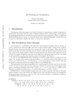
يمكن بناء ثماني سطوح منتظم في الفضاء $\mathbb{R}^3$، بدءًا من مربع في المستوى xy طول ضلعه $s$. يمر خط عمودي على هذا المستوى عبر مركز المربع. نأخذ نقطتين على هذا الخط (واحدة فوق المستوى والأخرى تحته)، بحيث تكون المسافة من كل منهما إلى أركان المربع الأربعة مساوية لـ $s$. هذه النقاط الست تشكل الرؤوس.
2.2 حساب إحداثيات الرؤوس
لنضع $s = 1$، تُعرّف نقاط زاوية المربع على النحو التالي: $p_0 = (0,0,0)$، $p_1 = (1,0,0)$، $p_2 = (1,1,0)$، $p_3 = (0,1,0)$. المحور الطبيعي هو المحور z المار عبر $(0.5, 0.5, 0)$. يتم الحصول على القمتين العلوية والسفلية $p_4$ و $p_5$ بحل معادلة المسافة من $(0.5, 0.5, \hat{z})$ إلى أي نقطة زاوية: $(0.5)^2 + (0.5)^2 + \hat{z}^2 = 1^2$. هذا يعطي $\hat{z} = \pm\sqrt{0.5} \approx \pm 0.707$. وبالتالي، $p_4 = (0.5, 0.5, 0.707)$، $p_5 = (0.5, 0.5, -0.707)$.
2.3 التنفيذ باستخدام OpenSCAD
في كود OpenSCAD، يتم تعريف القمم والأوجه لتوليد نموذج ثلاثي الأبعاد. يتم تعريف الأوجه عن طريق سرد مؤشرات القمم بترتيب عقارب الساعة.
polyhedron(
هذا ينشئ نموذجًا دقيقًا رياضيًا ولكنه غير قابل للطباعة مباشرة (الشكل 1 في ملف PDF).
3. مجسم ثماني السطوح للطباعة ثلاثية الأبعاد
لتكييف النموذج الرياضي مع التصنيع الفعلي، يجب معالجة القيود العملية لتقنية الطباعة ثلاثية الأبعاد.
3.1 قيود التصنيع
تم تحديد مشكلتين رئيسيتين: 1) الحجم الوحدي للنموذج (1 وحدة) صغير جدًا بالنسبة للطابعات ثلاثية الأبعاد النموذجية القائمة على المليمتر، مما يتطلب تغيير المقياس. 2) يجب أن يكون للجسم قاعدة مسطحة مستقرة على لوحة البناء (المستوى xy). إن مجرد نقل النموذج لجعل رأس واحد يلامس لوحة البناء غير كافٍ، لأن النقطة الحادة لا توفر الاستقرار.
يتم تطبيق الدوران $R$ على جميع القمم (يليها التحجيم)، مما ينتج عنه ثماني السطوح مستقر وقابل للطباعة ومستويًا على مستوى xy. القمم المحولة (محفوظة بثلاث منازل عشرية) هي:
4. التحليل الأساسي والرؤى التقنية
الرؤى الأساسية:يمثل عمل Aboufadel مثالًا ممتازًا على الفجوة التي غالبًا ما يتم تجاهلها بين النمذجة الرياضية البحتة والتصنيع الرقمي العملي. فهو يكشف عن حقيقة جوهرية: نماذج CAD الهندسية المثالية غالبًا ما تكون فاشلة من ناحية التصنيع. القيمة الحقيقية لهذا المقال لا تكمن في اشتقاق قمم ثماني السطوح (وهي مشكلة محلولة بالفعل)، بل في التوثيق الدقيق لخطوات المعالجة اللاحقة (الدوران، التحجيم) الضرورية لسد الفجوة بين الرقمي والمادي. وهذا يتوافق معمركز البتات والذرات بمعهد ماساتشوستس للتكنولوجيانتائج البحث للمركز، الذي يؤكد أن "التصميم من أجل التصنيع" هو تخصص مستقل يختلف عن التصميم الحسابي.
التدفق المنطقي:تتبع هذه المقالة سير عمل هندسي لا تشوبه شائبة: 1)تعريف(قيود هندسية)، 2)حل(حساب الإحداثيات)، 3)تنفيذ(كود OpenSCAD)، 4)التكيف(التوجه نحو التصنيع). وهذا يعكس العملية القياسية في أبحاث التصنيع الإضافي، كما هو موضح فيAdditive Manufacturingالمراجعات المنشورة في المجلات وما شابهها. ومع ذلك، تبرز هذه العملية بوضوح أن الخطوة 4 لا غنى عنها وعادة ما تكون أكثر تعقيدًا من التصميم الأولي.
المزايا والعيوب:تكمن ميزتها في الوضوح التعليمي والقابلية للتطبيق العملي. فهي توفر "وصفة" كاملة وقابلة للتكرار. من منظور صناعي، يكمن قصورها في طبيعتها اليدوية والمرة الواحدة. تم حل زاوية الدوران α تحليليًا لهذه الحالة المحددة. في برامج CAD/CAE المهنية، سيتم ذلك تلقائيًا بواسطة محلل قيود أو خوارزميات تصميم توليدية تأخذ في الاعتبار تلقائيًا اتجاه الطباعة وتقليل الدعامات، كما في أدوات مثل Autodesk Netfabb أو Siemens NX. لا يمكن توسيع نطاق منهجية هذه الورقة لتناسب الأشكال الهندسية المعقدة وغير المنتظمة.
رؤى قابلة للتطبيق:بالنسبة للمعلمين، فهذه الوحدة مثالية لدمج الرياضيات والهندسة في مناهج STEM. بالنسبة للممارسين، النقطة الرئيسية هيدائمًاضع في الاعتبار استقرار المحور والقاعدة منذ البداية. يجب أن يوجه هذه العملية اختيار نظام الإحداثيات الأولي. بالإضافة إلى ذلك، يوضح دراسة الحالة هذه الحاجة إلى تطوير إضافات "فحص قابلية الطباعة" لأدوات مفتوحة المصدر مثل OpenSCAD لأتمتة التحليل الذي تم إجراؤه يدويًا في هذا البحث. يكمن المستقبل في تضمين قيود التصنيع مباشرة في حلقة التصميم التوليدي.
المعادلة الأساسية (الدوران): $\frac{1}{2}\sin\alpha + \frac{\sqrt{2}}{2}\cos\alpha = 0$. مُشتقة من كون المركبة z لـ $R p_4$ تساوي صفر.
الحل: $\tan\alpha = -\sqrt{2}$، مما يؤدي إلى $\sin\alpha = \sqrt{2/3}$، $\cos\alpha = -\sqrt{1/3}$، $\alpha \approx -54.74^\circ$.
التحويل:تطبيق المصفوفة $R$ على جميع الرؤوس $p_0...p_5$، للحصول على الإحداثيات القابلة للطباعة $\hat{p}_0...\hat{p}_5$.
نتائج التجارب ووصف المخططات
تقدم هذه الورقة نتيجتين بصريتين رئيسيتين (الشكل):
الشكل 1 (النموذج الأولي):تم عرض مجسم ثماني السطوح الصحيح رياضياً والمولد من مقتطف كود OpenSCAD الأول. يظهر الشكل برأس مباشرة فوق القاعدة المربعة ورأس آخر مباشرة تحتها، مما يعني أن النموذج، إذا طُبع، سيتوازن على نقطة حادة.
الشكل 2 (النموذج القابل للطباعة):يُظهر الشكل الثماني السطوح بعد تطبيق مصفوفة الدوران $R$. يكمن الاختلاف البصري الرئيسي في أن أحد الأوجه المثلثية أصبح الآن مستويًا ومحاذيًا للمستوى الأفقي (لوح البناء الافتراضي)، مشكلاً قاعدة مستقرة ومسطحة. جميع القمم لها إحداثيات z غير سالبة، مما يؤكد ملاءمتها للتصنيع الطبقي بدءًا من z=0.
يتحقق التحقق من ضرورة الاشتقاق الرياضي وخطوات التحويل بنجاح من خلال توليد هذين النموذجين المختلفين.
5. إطار التحليل وأمثلة الحالات
إطار التحليل "التصميم الموجه للطباعة ثلاثية الأبعاد":
تستخدم هذه المقالة ضمنيًا إطار عمل مناسبًا لتحويل أي نموذج هندسي إلى تصنيع إضافي. يمكن صياغة خطواته على النحو التالي:
التعريف الهندسي:تعريف الكائن باستخدام قيود رياضية (رؤوس، أوجه، معادلات).
النمذجة الأولية الرقمية:تنفيذ التعريف في برنامج CAD (مثل OpenSCAD، أو نصوص Python) لتوليد شبكة ثلاثية الأبعاد.
مراجعة قابلية الطباعة:التحقق مقابل القيود الفيزيائية:
استقرار القاعدة:هل هناك أي وجه/منطقة يلامس لوح البناء؟
الاتجاه:هل يقلل هذا الاتجاه من الحاجة إلى الدعامات أو التعليق؟
التحجيم:هل الأبعاد ضمن النطاق القابل للطباعة؟ (على سبيل المثال، مقياس المليمتر)
سلامة الهيكل:هل توجد ميزات غير مدعمة قد تفشل؟
تحويل النموذج:تطبيق التحويلات الهندسية (النقل، الدوران، التحجيم) لتلبية متطلبات المراجعة في الخطوة 3.
تصدير الملف والتقطيع:تصدير إلى صيغة قياسية (STL، 3MF) ومعالجتها في برنامج التقطيع لإنشاء كود G.
مثال حالة (إطار تطبيق): المشكلة:طباعة رباعي وجوه منتظم طول ضلعه 10 ملم. 步骤1 & 2:تعريف النقاط الرأسية، مثل (0,0,0)، (10,0,0)، (5, 8.66, 0)، (5, 2.89, 8.16). النمذجة في CAD. الخطوة 3 المراجعة:تم وضع النموذج على وجه مثلثي (مستقر جيدًا). ومع ذلك، فإن النقطة الرأسية لذلك الوجه هي z=0، والنقاط داخل الوجه أيضًا عند z=0، مما يشكل قاعدة مثالية. المقياس صحيح (10 ملم). الخطوة 4: التحويلفي هذه الحالة، يكون الاتجاه الأولي هو الأمثل بالفعل. لا حاجة للدوران، قد تكون هناك حاجة فقط للإزاحة لتركيز النموذج على لوحة البناء.
يوضح هذا المثال كيف يمكن للإطار أن يوجه عملية اتخاذ القرار، مما قد يوفر الوقت والمواد مقارنة بطريقة التجربة والخطأ.
6. التطبيقات المستقبلية والاتجاهات
المبادئ المعروضة لها أهمية تتجاوز متعدد السطوح الفردي:
مجموعة الأدوات التعليمية:أتمتة هذه العملية من خلال تطوير إضافات برمجية لمنصات مثل OpenSCAD أو Blender، تسمح للطلاب بإدخال معايير مجسمات أفلاطون وتوليد نماذج مطبوعة مُحسنة تلقائيًا.
الشبكات المتقدمة والمواد الفائقة:هياكل خلايا دورية معقدة، حاسمة في مجال الطيران والفضاء والغرسات الطبية الحيوية (مستوحاة منLawrence Livermore National Laboratoryأبحاث المواد المعمارية)، تتطلب تحسينًا مشابهًا للتوجيه لضمان قابلية الطباعة والأداء الميكانيكي.
التكامل مع الذكاء الاصطناعي التوليدي:دمج نماذج الذكاء الاصطناعي من النص إلى ثلاثي الأبعاد أو من الصورة إلى ثلاثي الأبعاد مع وحدة "محسن قابلية الطباعة" اللاحقة. يولد الذكاء الاصطناعي الأشكال، بينما يقوم المحسن بتعديلها وفقًا لقواعد مستمدة من منطق هذه الورقة البحثية لتلائم التصنيع.
المواد المتعددة والطباعة بدون دعائم:قد تشمل التطورات المستقبلية خوارزميات لا تعيد توجيه النموذج فحسب، بل تقترح أيضًا تقسيمه إلى مكونات فرعية أو تخصيص مواد مختلفة لتسهيل الطباعة بدون دعائم، وهو مجال بحثي رئيسي في التصنيع المضاف الحديث.
توحيد "درجة قابلية الطباعة":تطوير مقاييس كمية تعتمد على القدرات الهندسية والطابعة للتنبؤ بمعدل النجاح، على غرارInternational Journal of Advanced Manufacturing Technologyالعمل المشار إليه في
7. المراجع
Aboufadel, E. (2014). طباعة مجسم ثماني الوجوه ثلاثي الأبعاد. Grand Valley State University. arXiv:1407.5057v1.
Gibson, I., Rosen, D., & Stucker, B. (2021). تقنيات التصنيع الإضافي: الطباعة ثلاثية الأبعاد، والنمذجة السريعة، والتصنيع الرقمي المباشر. Springer. (حول مبادئ التصميم الشاملة الموجهة للتصنيع الإضافي).
MIT Center for Bits and Atoms. (2023). البحث: التصنيع الرقمي. تم الاسترجاع من https://cba.mit.edu/. (حول فلسفة التكامل من التصميم إلى التصنيع).
Zhu, J., et al. (2017). استخدام شبكات الخصومة ذات الاتساق الدوري للتحويل غير المزدوج من صورة إلى صورة. ICCV. (CycleGAN كمثال لنموذج التحويل، يشبه خطوة تحويل النموذج).
Brackett, D., Ashcroft, I., & Hague, R. (2011). التحسين الطوبولوجي الموجه للتصنيع الإضافي. Proceedings of the Solid Freeform Fabrication Symposium. (خلفية متقدمة حول التحسين التلقائي للتصميم الموجه للتصنيع الإضافي).
International Journal of Advanced Manufacturing Technology. (متنوع). عدد خاص: التصميم الموجه للتصنيع الإضافي. Springer. (آخر التطورات في تحليل القابلية للطباعة).
الرؤى الأساسية:يمثل عمل Aboufadel مثالًا ممتازًا على الفجوة التي غالبًا ما يتم تجاهلها بين النمذجة الرياضية البحتة والتصنيع الرقمي العملي. فهو يكشف عن حقيقة جوهرية: نماذج CAD الهندسية المثالية غالبًا ما تكون فاشلة من ناحية التصنيع. القيمة الحقيقية لهذا المقال لا تكمن في اشتقاق قمم ثماني السطوح (وهي مشكلة محلولة بالفعل)، بل في التوثيق الدقيق لخطوات المعالجة اللاحقة (الدوران، التحجيم) الضرورية لسد الفجوة بين الرقمي والمادي. وهذا يتوافق معمركز البتات والذرات بمعهد ماساتشوستس للتكنولوجيانتائج البحث للمركز، الذي يؤكد أن "التصميم من أجل التصنيع" هو تخصص مستقل يختلف عن التصميم الحسابي.
التدفق المنطقي:تتبع هذه المقالة سير عمل هندسي لا تشوبه شائبة: 1)تعريف(قيود هندسية)، 2)حل(حساب الإحداثيات)، 3)تنفيذ(كود OpenSCAD)، 4)التكيف(التوجه نحو التصنيع). وهذا يعكس العملية القياسية في أبحاث التصنيع الإضافي، كما هو موضح فيAdditive Manufacturingالمراجعات المنشورة في المجلات وما شابهها. ومع ذلك، تبرز هذه العملية بوضوح أن الخطوة 4 لا غنى عنها وعادة ما تكون أكثر تعقيدًا من التصميم الأولي.
المزايا والعيوب:تكمن ميزتها في الوضوح التعليمي والقابلية للتطبيق العملي. فهي توفر "وصفة" كاملة وقابلة للتكرار. من منظور صناعي، يكمن قصورها في طبيعتها اليدوية والمرة الواحدة. تم حل زاوية الدوران α تحليليًا لهذه الحالة المحددة. في برامج CAD/CAE المهنية، سيتم ذلك تلقائيًا بواسطة محلل قيود أو خوارزميات تصميم توليدية تأخذ في الاعتبار تلقائيًا اتجاه الطباعة وتقليل الدعامات، كما في أدوات مثل Autodesk Netfabb أو Siemens NX. لا يمكن توسيع نطاق منهجية هذه الورقة لتناسب الأشكال الهندسية المعقدة وغير المنتظمة.
رؤى قابلة للتطبيق:بالنسبة للمعلمين، فهذه الوحدة مثالية لدمج الرياضيات والهندسة في مناهج STEM. بالنسبة للممارسين، النقطة الرئيسية هيدائمًاضع في الاعتبار استقرار المحور والقاعدة منذ البداية. يجب أن يوجه هذه العملية اختيار نظام الإحداثيات الأولي. بالإضافة إلى ذلك، يوضح دراسة الحالة هذه الحاجة إلى تطوير إضافات "فحص قابلية الطباعة" لأدوات مفتوحة المصدر مثل OpenSCAD لأتمتة التحليل الذي تم إجراؤه يدويًا في هذا البحث. يكمن المستقبل في تضمين قيود التصنيع مباشرة في حلقة التصميم التوليدي.