Table of Contents
1. Introduction
This paper outlines a project to manufacture a regular octahedron using a 3D printer. It bridges fundamental geometric principles with practical digital fabrication techniques. The process involves calculating the polyhedron's vertices and faces, creating a virtual 3D model in OpenSCAD, generating an STL file, and finally producing the physical object. The project assumes basic familiarity with 3D printing concepts.
2. The Octahedron: First Attempt
A regular octahedron is a Platonic solid with eight equilateral triangular faces and six vertices. The initial mathematical model serves as the foundation for digital creation.
2.1 Geometric Construction
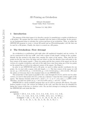
The octahedron can be constructed in $\mathbb{R}^3$ by starting with a square of side length $s$ in the xy-plane. A line normal to the plane passes through the square's center. Two points on this line (one above, one below the plane) are determined such that their distance to all four corners of the square equals $s$. These six points (the four square corners and the two axial points) form the vertices.
2.2 Vertex Coordinate Calculation
Setting $s = 1$ for simplicity, the square corners are defined as:
- $p_0 = (0.0, 0.0, 0.0)$
- $p_1 = (1.0, 0.0, 0.0)$
- $p_2 = (1.0, 1.0, 0.0)$
- $p_3 = (0.0, 1.0, 0.0)$
The center is at $(0.5, 0.5, 0)$. The axial points $(0.5, 0.5, \hat{z})$ must satisfy the distance condition: $(0.5)^2 + (0.5)^2 + \hat{z}^2 = 1^2$. Solving yields $\hat{z}^2 = 0.5$, so $\hat{z} = \pm\sqrt{0.5} \approx \pm 0.707$.
Thus, the final vertices are:
- $p_4 = (0.5, 0.5, 0.707)$
- $p_5 = (0.5, 0.5, -0.707)$
2.3 OpenSCAD Implementation
The vertices and faces are defined in OpenSCAD code. Faces are listed by their vertex indices in clockwise order.
polyhedron(
    points = [[0.0, 0.0, 0.0], [1.0, 0.0, 0.0], [1.0, 1.0, 0.0],
              [0.0, 1.0, 0.0], [0.5, 0.5, 0.707], [0.5, 0.5, -0.707]],
    triangles = [[4, 1, 0], [4, 2, 1], [4, 3, 2], [4, 0, 3],
                 [5, 0, 1], [5, 1, 2], [5, 2, 3], [5, 3, 0]]
);
This creates a mathematically accurate but practically unsuitable model for 3D printing.
3. The Octahedron to 3D Print
Adapting the mathematical model for physical manufacturing requires addressing scale and orientation constraints inherent to Fused Deposition Modeling (FDM) 3D printers.
3.1 Manufacturing Constraints
Two main issues arise:
- Scale: The 1mm model is too small. Printers typically use millimeters, requiring scaling.
- Orientation & Base: Objects are built layer-by-layer from the build plate (z=0). A model must have a stable, flat base for adhesion, not a sharp vertex touching the plate.
3.2 Rotation Transformation
A rotation about the x-axis is applied so that vertex $p_4$ moves to the xy-plane, creating a flat triangular face as the base. The rotation matrix is: $$R = \begin{bmatrix} 1 & 0 & 0 \\ 0 & \cos\alpha & -\sin\alpha \\ 0 & \sin\alpha & \cos\alpha \end{bmatrix}$$ Applying it to $p_4 = (0.5, 0.5, 0.707)$ and setting the resulting z-coordinate to zero gives the condition: $$\frac{1}{2}\sin\alpha + \frac{\sqrt{2}}{2}\cos\alpha = 0 \Rightarrow \tan\alpha = -\sqrt{2}$$ Solving yields $\sin\alpha = \sqrt{6}/3$, $\cos\alpha = -\sqrt{3}/3$, with $\alpha \approx -54.74^\circ$.
3.3 Final Model for Printing
Applying rotation $R$ to all vertices (and scaling appropriately for desired size) produces the final coordinates for printing, with all $z \ge 0$:
- $\hat{p}_0 = (0.0, 0.0, 0.0)$
- $\hat{p}_1 = (1.0, 0.0, 0.0)$
- $\hat{p}_2 = (1.0, -0.577, 0.816)$
- $\hat{p}_3 = (0.0, -0.577, 0.816)$
- $\hat{p}_4 = (0.5, -0.865, 0.0)$
- $\hat{p}_5 = (0.5, 0.288, 0.816)$
4. Core Analysis & Expert Interpretation
Core Insight: This paper is a quintessential case study in the often-underestimated gap between pure mathematical modeling and practical digital fabrication. It demonstrates that a "correct" 3D model is not synonymous with a "printable" one. The core value lies not in creating an octahedron—a trivial task in modern CAD—but in explicitly detailing the necessary geometric transformation (a specific rotation) to bridge this gap for a specific manufacturing constraint (FDM printing). This process mirrors the "slicing" and "support generation" logic in software like Cura or PrusaSlicer, but at a fundamental, user-controlled level.
Logical Flow: The author's methodology is impeccably logical and pedagogically sound: 1) Define the ideal mathematical object, 2) Implement it in a neutral digital environment (OpenSCAD), 3) Identify the constraints of the target physical system (the 3D printer's build plate and layer adhesion), 4) Derive and apply the precise transformation (rotation) that aligns the model with system constraints while preserving geometric integrity. This flow is a microcosm of the engineering design process, moving from abstract concept to manufacturable design.
Strengths & Flaws: The primary strength is its clarity and focus on first principles. It avoids reliance on black-box software fixes, teaching users why a rotation of approximately $-54.74^\circ$ is necessary, not just how to click "lay flat" in a slicer. This foundational understanding is crucial for tackling more complex, non-symmetric printing challenges. However, the paper's major flaw is its dated simplicity. It addresses only one basic constraint (a flat base). Modern 3D printing challenges involve overhang angles (the $45^\circ$ rule), thermal stress, support structure optimization, and anisotropic material properties—topics explored in depth by institutions like MIT's Center for Bits and Atoms or in research on topology optimization for additive manufacturing. The solution is also manual; contemporary approaches, as seen in Autodesk Netfabb or research on automated build orientation optimization, use algorithms to evaluate multiple orientations against a weighted set of constraints (support volume, surface quality, print time).
Actionable Insights: For educators, this paper remains a perfect introductory module for courses blending math, computer science, and engineering. It should be followed by modules introducing automated orientation algorithms. For practitioners, the takeaway is to always separate the "canonical" model from the "manufacturing-ready" model in their workflow. The canonical model is the design truth; the manufacturing model is a derivative adapted to process constraints. This separation ensures design intent is preserved and can be adapted to different manufacturing methods (e.g., rotating differently for SLA printing vs. FDM). Furthermore, this case underscores the value of understanding the underlying mathematics of transformations, as it empowers designers to move beyond the limitations of pre-set software tools.
5. Technical Details & Mathematical Formulation
The key technical derivation is the rotation transformation. The condition for vertex $p_4$ to land on the z=0 plane after rotation by $\alpha$ about the x-axis is derived from applying the rotation matrix: $$R\cdot p_4 = \begin{bmatrix} 0.5 \\ 0.5\cos\alpha - 0.707\sin\alpha \\ 0.5\sin\alpha + 0.707\cos\alpha \end{bmatrix}$$ Setting the third component to zero: $0.5\sin\alpha + 0.707\cos\alpha = 0$. Using $0.707 \approx \sqrt{2}/2$, the equation simplifies to $\tan\alpha = -\sqrt{2}$. This yields the exact trigonometric solutions: $$\sin\alpha = \frac{\sqrt{6}}{3}, \quad \cos\alpha = -\frac{\sqrt{3}}{3}$$ The negative cosine indicates an angle greater than $90^\circ$ in standard position, but here it represents a clockwise rotation of about $54.74^\circ$ from the initial configuration.
6. Results & Visual Output
The paper references two key figures (simulated here descriptively):
- Figure 1 (Initial Model): Shows the mathematically perfect octahedron generated from the first OpenSCAD code. It is symmetrical along the z-axis, with one vertex pointing directly up and one directly down. It appears as two square-based pyramids joined at their bases.
- Figure 2 (Rotated Model): Shows the transformed octahedron after the $-54.74^\circ$ rotation. The model now rests on one of its equilateral triangular faces on the virtual build plate (xy-plane). All other vertices have positive z-coordinates, making the entire model lie above the plate, ready for layer-by-layer fabrication without any part being "inside" the build plate.
The successful print would result in a physical regular octahedron with a flat, stable bottom face, demonstrating the practical application of the derived transformation.
7. Analysis Framework: A Non-Code Case Study
Scenario: A museum wants to 3D print a delicate, intricate mathematical sculpture of a "Gyroid" minimal surface for an exhibit. The digital model is perfect but highly complex, with many overhangs.
Applying the Framework from the Paper:
- Canonical Model: The Gyroid surface defined by the equation $\cos(x)\sin(y) + \cos(y)\sin(z) + \cos(z)\sin(x) = 0$.
- Manufacturing Constraint Identification: The primary constraint is not a base, but excessive overhangs exceeding $45^\circ$, which would cause print failure without supports. Supports mar surface finish.
- Transformation Derivation: Instead of a simple rotation for a base, the problem requires finding an orientation that minimizes the total area of overhanging surfaces beyond a critical angle. This is a multi-variable optimization problem.
- Solution: Use an algorithmic approach (e.g., ray-casting from various orientations to measure overhang area) to evaluate hundreds of potential rotations ($\alpha, \beta, \gamma$). The optimal orientation is chosen to minimize support needs, trading off against increased build height or stair-stepping on certain curves.
8. Future Applications & Directions
The principles demonstrated have broad implications beyond simple polyhedra:
- Educational Tools: Automating the process for any Platonic or Archimedean solid, allowing students to input a solid and receive both canonical and print-ready models, deepening understanding of symmetry and transformation.
- Biomedical Printing: Applying similar constraint-aware transformations to models of anatomical structures (e.g., bones) for printing with biocompatible materials, where orientation affects mechanical strength and surface interaction with tissue.
- Construction & Architecture: Scaling the concept for large-scale additive manufacturing of building components. Orientation during printing affects layer adhesion strength and resistance to forces like wind or gravity. Research at institutions like ETH Zurich's Digital Building Technologies group explores this.
- Integrated Design Systems: The future lies in generative design systems where the manufacturing constraints (like the need for a flat base or overhang limits) are input parameters from the start. The design algorithm, informed by research like that from the Additive Manufacturing journal, generates shapes that are inherently optimized for printability, eliminating the need for post-design transformations.
9. References
- Aboufadel, E. (2014). 3D Printing an Octohedron. arXiv preprint arXiv:1407.5057.
- Gibson, I., Rosen, D., & Stucker, B. (2015). Additive Manufacturing Technologies: 3D Printing, Rapid Prototyping, and Direct Digital Manufacturing (2nd ed.). Springer. (For comprehensive manufacturing constraints).
- Paul, R., & Anand, S. (2015). Optimization of Layered Manufacturing Process for Reducing Form Errors with Minimal Support Structures. Journal of Manufacturing Systems, 36, 231-243. (For automated orientation algorithms).
- MIT Center for Bits and Atoms. (n.d.). Research on Digital Fabrication. Retrieved from [External Link: https://cba.mit.edu/]. (For advanced applications).
- Autodesk Netfabb. (2023). Advanced Build Preparation and Optimization White Paper. (For commercial software approaches to orientation).