1. Introduction & Overview
This research explores the application of Fused Deposition Modeling (FDM) 3D printing for fabricating fluidic soft logic gates, specifically focusing on soft bistable valves. The primary objective is to address the limitations of existing fabrication methods—such as extensive manual processes (e.g., replica molding) and expensive printing techniques—by developing a rapid, cost-effective, and automated alternative using desktop FDM printers.
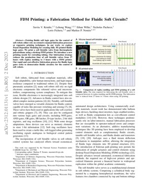
The core innovation lies in introducing a new printing nozzle capable of extruding tubing directly, enabling the creation of fully 3D printed, functional fluidic logic elements from thermoplastic polyurethane (TPU). This approach significantly reduces production time from 27 hours (with traditional methods) to just 3 hours, aiming to democratize access to fluidic circuitry for soft robotic control systems.
2. Methodology & Fabrication
The fabrication strategy centers on using a standard desktop FDM printer modified with a custom nozzle designed for extruding flexible tubing material. The primary material is thermoplastic polyurethane (TPU), chosen for its elasticity and durability, suitable for creating the soft, compliant components of the bistable valve.
2.1 FDM Printing Process
The process involves printing the valve's cylindrical body, hemispherical snapping membrane, end caps, and integrated tubing in a single, continuous print job or minimal assemblies. The custom nozzle allows for precise deposition of the tubing material, ensuring airtight seals and functional fluidic channels. Key print parameters include layer height, print speed, and temperature, optimized for TPU to achieve the necessary mechanical properties for valve operation.
2.2 Valve Design & Components
The soft bistable valve consists of a cylindrical body segmented by a snapping hemispherical membrane. It features two chambers connected via top and bottom tubing to the membrane and end caps. The design parameters, such as membrane thickness, chamber volume, and tubing diameter, are critical for achieving the bistable snapping behavior—where the membrane rapidly transitions between two stable states upon reaching a critical pressure threshold.
The CAD design allows for tuning these parameters to create both monostable and bistable configurations, as illustrated in Figure 2 of the PDF. The influential parameters include the radius of curvature of the membrane, the chamber height, and the port diameters.
3. Technical Details & Mathematical Model
The operation of the bistable valve relies on the snap-through instability of the hemispherical membrane. This can be modeled using thin-shell theory and energy principles. The critical pressure ($P_{crit}$) required to snap the membrane from one stable state to another can be approximated by considering the strain energy and the work done by the pressure.
A simplified model for the critical pressure can be derived from the balance of energies:
$\Delta U_{elastic} = \int P \, dV$
Where $\Delta U_{elastic}$ is the change in elastic strain energy of the membrane, $P$ is the applied pressure, and $dV$ is the change in volume of the chamber. For a spherical cap membrane with radius $R$, thickness $t$, and Young's modulus $E$, the critical pressure can be related to these parameters and the Poisson's ratio $\nu$. A more detailed analysis often involves solving the Föppl–von Kármán equations for large deflections of thin plates/shells.
The hysteresis behavior—a key feature of bistability—is governed by the difference in energy barriers between the two transition paths. The valve remains in its last state after actuation, functioning as a mechanical memory element, which is fundamental for constructing sequential logic circuits like latches and shift registers.
4. Experimental Results & Performance
The experimental validation focused on two main aspects: fabrication efficiency and valve functionality.
4.1 Fabrication Time Comparison
Fabrication Time Reduction
Replica Molding: 27 hours
FDM Printing: 3 hours
Improvement: 89% reduction in time
As depicted in Figure 1 of the PDF, the FDM printing method drastically reduces the total fabrication time from 27 hours (involving multiple steps like mold creation, casting, curing, and assembly in replica molding) to approximately 3 hours. This 89% reduction is primarily due to the automation and integration offered by 3D printing, eliminating most manual labor and waiting periods.
4.2 Valve Functionality Testing
The 3D printed valves were tested for their switching characteristics, response time, and reliability. The valves successfully demonstrated bistable behavior, snapping between two distinct states at a designed critical pressure. The integrated tubing showed no leaks at operational pressures, confirming the effectiveness of the custom nozzle and print strategy in creating airtight fluidic paths.
The valves were capable of basic logic operations (e.g., acting as a NOT-gate) and could be interconnected to form more complex circuits. The research indicates that the performance of the FDM-printed valves is comparable to those made via traditional methods in terms of functionality, while offering superior fabrication speed and potential for design customization.
5. Analysis Framework & Case Study
Framework for Evaluating Soft Fluidic Fabrication Methods:
To critically assess this and similar works, we propose a multi-axis evaluation framework:
- Fabrication Accessibility: Cost of equipment (printer, nozzle), material availability, required operator skill level.
- Performance Metrics: Switching speed, operating pressure range, hysteresis width, durability (cycle life).
- Design Freedom & Integration: Ability to create complex geometries, embed multiple components, and interface with other soft robotic parts.
- Scalability & Reproducibility: Consistency across printed parts, potential for mass production.
Case Study: Soft Robotic Gripper Control
Consider a soft robotic gripper that needs to alternate between two gripping modes (e.g., pinch and enveloping grasp) based on object detection. A traditional electronic control system would use sensors, a microcontroller, and solenoid valves.
Fluidic Logic Alternative using FDM-Printed Valves:
- Input: A soft pressure sensor (e.g., a resistive channel) detects contact and sends a fluidic signal (pressure pulse).
- Processing: The signal is fed into a fluidic circuit built from FDM-printed bistable valves configured as an SR-latch. The latch "remembers" the last detected object type.
- Output: The state of the latch controls a pneumatic distributor, directing airflow to either the pinch or enveloping actuator chamber in the gripper.
This case demonstrates a fully soft, embodied control system where sensing, logic, and actuation are all fluidic and compliant, eliminating rigid electronics. The FDM method allows for rapid prototyping and customization of the logic circuit to fit the specific gripper geometry.
6. Critical Analysis & Expert Interpretation
Core Insight: This paper isn't just about a faster way to make a valve; it's a strategic pivot towards democratization through deskilling. The real breakthrough is the custom nozzle that turns a $500 desktop FDM printer into a fluidic circuit fab. By targeting the bottleneck of manual tubing integration, the authors have effectively decoupled complex soft robot functionality from artisan-level fabrication skills. This mirrors the trajectory of electronic prototyping, where platforms like Arduino abstracted away low-level hardware complexities. The goal is clear: to make fluidic computation as accessible as blinking an LED on a microcontroller board.
Logical Flow & Strategic Positioning: The argument is compellingly linear. Start with the problem: soft robots are held back by rigid control systems. Present the promising solution: fluidic logic. Identify the adoption barrier: tedious, skill-dependent fabrication. Then, deliver the enabler: automated, low-cost FDM printing. The paper cleverly positions itself not against high-end, multi-material printers (like PolyJet or SLA used in related work), but against the manual bench work that dominates academic labs. It's a pragmatic play for widespread academic adoption first, which can then drive commercial interest.
Strengths & Flaws: The 89% time reduction is a knockout punch—it changes the economics of experimentation. The use of TPU, a common, low-cost filament, is a major strength for replicability. However, the analysis is glaringly silent on long-term durability. Soft robotics famously grapples with material fatigue and creep, especially in cyclically loaded elastomers. How many actuation cycles can this printed TPU membrane withstand before failing? Without this data, it's a brilliant prototype but an unproven product. Furthermore, while the nozzle innovation is key, its design and performance specifications are underexplored—the "secret sauce" is somewhat opaque, which could hinder community replication, ironically counter to the democratization goal.
Actionable Insights: For researchers: This is a blueprint to follow. The immediate next step is to characterize the fatigue life and pressure-cycle reliability of these valves. For industry (especially startups in soft grippers or wearable tech): This method slashes R&D iteration time. Partner with the authors or develop similar nozzles to rapidly prototype entirely soft, fluidically controlled devices. The biggest opportunity lies in hybrid systems. Don't see this as replacing all electronics, but as enabling robust, waterproof, and EMI-immune control subsystems in harsh environments (e.g., underwater, in MRI machines, or in explosive atmospheres) where traditional electronics fail. The future isn't all-fluidic or all-electronic; it's about strategically deploying each where it excels.
7. Future Applications & Development
The implications of this work extend beyond academic prototyping:
- Wearable and Biomedical Devices: Fully soft, implantable, or wearable drug delivery systems that use fluidic logic for timed release sequences, without any electronic components that could cause interference or require batteries.
- Resilient Robotics for Extreme Environments: Robots operating in high-radiation, deep-sea, or space environments where electronics are vulnerable. Fluidic logic circuits printed as integral parts of the robot's body would offer unparalleled resilience.
- Educational Kits: Low-cost, safe classroom kits for teaching computational thinking and robotics principles using tangible fluidic circuits instead of virtual code.
- Sustainable Disposables: Single-use medical or diagnostic devices with embedded control logic, made from biodegradable thermoplastics, combining functionality with environmental responsibility.
Future Research Directions:
- Material Science: Developing FDM filaments with enhanced properties—self-healing, higher fatigue resistance, or stimuli-responsive (e.g., temperature, pH) behavior to create adaptive valves.
- Multi-Material Printing: Integrating conductive or piezoresistive materials within the same print to create hybrid fluidic-electronic sensors and interfaces seamlessly.
- Algorithmic Design Tools: Creating software that automatically converts a digital logic circuit diagram into an optimized, 3D-printable fluidic network layout, similar to electronic PCB design software.
- Standardization: Establishing performance benchmarks, connector standards, and design libraries for fluidic logic components to accelerate community-driven development, akin to the role of the MIT Fluidic Logic Library in earlier work.
8. References
- Rus, D., & Tolley, M. T. (2015). Design, fabrication and control of soft robots. Nature, 521(7553), 467-475.
- Rich, S. I., Wood, R. J., & Majidi, C. (2018). Untethered soft robotics. Nature Electronics, 1(2), 102-112.
- Wehner, M., et al. (2016). An integrated design and fabrication strategy for entirely soft, autonomous robots. Nature, 536(7617), 451-455.
- Mosadegh, B., et al. (2014). Pneumatic networks for soft robotics that actuate rapidly. Advanced Functional Materials, 24(15), 2163-2170.
- Onal, C. D., Chen, X., Whitesides, G. M., & Rus, D. (2017). Soft mobile robots with on-board chemical pressure generation. In Robotics Research (pp. 525-540). Springer.
- Preston, D. J., et al. (2019). Digital logic for soft devices. Proceedings of the National Academy of Sciences, 116(16), 7750-7759.
- Nemitz, M. P., et al. (2020). Using bistable valves to enable complex, pneumatic, soft robotic control. IEEE Robotics and Automation Letters, 5(2), 820-826.
- MIT Fluidic Logic Library. (n.d.). Retrieved from MIT Soft Robotics Toolkit website.
- Zhu, M., et al. (2020). Soft, wearable robotics and sensors: Challenges and opportunities. Advanced Intelligent Systems, 2(8), 2000071.
- Ionov, L. (2018). 4D Biofabrication: Materials, Methods, and Applications. Advanced Healthcare Materials, 7(17), 1800412.