Home »
Documentation »
Geometry Limitations in Indirect Selective Laser Sintering of Alumina
1. Introduction
This paper investigates the geometric design limitations for manufacturing ceramic components with open channels using Indirect Selective Laser Sintering (SLS). While complex ceramic architectures are crucial for clean energy technologies, established design rules for their additive manufacturing are lacking. The research compares existing geometry limitations developed for polymer SLS to their applicability in indirect SLS of alumina, identifying unique constraints inherent to the ceramic-binder powder system.
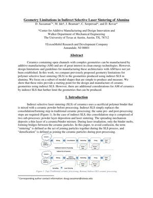
Key Process: Indirect SLS uses a sacrificial polymer binder (e.g., nylon) mixed with ceramic powder (alumina). During laser processing, only the binder sinters, forming a "green" part. Full densification of the ceramic occurs in subsequent post-processing steps like debinding and sintering, analogous to traditional ceramic processing but with a complex, AM-formed shape.
2. Materials and Methods
2.1 Materials
The study uses a powder blend of 78 wt.% fine alumina (Almatis A16 SG, d50=0.3µm) and 22 wt.% PA12 nylon (d50=58µm). The powders are dry-mixed and sieved, resulting in a morphology where fine alumina particles coat larger nylon particles (see schematic and SEM images in the PDF).
2.2 Methods: SLS Machine
Parts were built on a custom open-architecture SLS machine (LAMPS) at UT Austin. Process parameters were empirically optimized to minimize binder degradation and part curl:
Laser Power: 4 - 10 W
Scan Speed: 200 - 1000 mm/s
Layer Thickness: 100 µm
Hatch Spacing: 275 µm
Laser Spot Size (1/e²): 730 µm
3. Core Insight & Logical Flow
Core Insight: The central, unspoken truth of this paper is that indirect SLS for ceramics is a game of managing compromise between geometric freedom and material integrity. You cannot simply port polymer SLS design rules to ceramics and expect success. The polymer binder acts as a temporary, weak scaffold for the ceramic particles. This introduces a critical vulnerability during the "green" state that doesn't exist in monolithic polymer parts. The research flow logically tests polymer-derived rules (e.g., minimum feature size, overhang angles) on alumina, finds them necessary but insufficient, and systematically catalogs the new failure modes unique to the ceramic-powder-binder system, such as distortion during debinding or collapse of thin walls before sintering.
4. Strengths & Flaws
Strengths: The paper's methodology is pragmatic and valuable. Using a known polymer SLS benchmark (Allison et al.'s metrology part) provides a controlled baseline for comparison. The focus on "simple to produce and measure" model shapes is wise—it isolates geometric variables from other process noise. The use of a custom, sensor-rich machine (LAMPS) for parameter development is a significant advantage, allowing for precise control often missing in commercial black-box systems.
Flaws & Gaps: The major flaw is the lack of quantitative, predictive models. The work is largely empirical—it catalogs phenomena but doesn't provide a physics-based framework to predict, for instance, the minimum strut diameter as a function of powder morphology and binder content. It hints at but does not deeply analyze the role of post-processing (debinding/sintering) shrinkage and distortion, which are often the dominant factors in final geometric accuracy for ceramics. As noted in comprehensive reviews of ceramic AM like those by Zocca et al. (Journal of the European Ceramic Society), shrinkage can be anisotropic and non-linear, severely complicating design.
5. Actionable Insights
For engineers and designers:
Start with Polymer Rules, Then Add a Safety Factor: Use established polymer SLS design guidelines (e.g., from Stratasys or EOS) as a first draft, but immediately derate them. If the polymer rule says a 0.8mm wall is possible, design for 1.2mm in ceramic.
Design for the Green State: The weakest link is the unsintered "green" part. Avoid cantilevers and long, thin unsupported features that must survive handling before furnace processing. Incorporate temporary supports not just for overhangs but for structural rigidity during post-processing.
Embrace Hybrid Design-Process Co-Development: Do not design in a vacuum. Work iteratively with the process parameters (laser power, scan strategy) and the powder formulation (binder percentage, particle size distribution). A slight change in binder viscosity can enable steeper overhangs.
Quantify Post-Processing Distortion: Build calibration artifacts to measure shrinkage and warpage specific to your part geometry and furnace cycle. Use this data to inform compensatory scaling in the CAD model, a concept similar to the distortion compensation used in metal AM.
6. Technical Details & Experimental Results
The paper adapts a metrology part from polymer SLS research to test geometric limits. Key tested features likely include:
Angular Features: Maximum unsupported overhang angle, minimum achievable acute angle.
Expected Results & Phenomena: While specific data is not in the provided excerpt, based on similar studies (e.g., Nissen et al. on helical glass channels), we can infer:
Polymer SLS rules will be violated for down-facing surfaces due to poorer powder bed support and the need for the binder to coalesce.
Feature resolution will be worse than polymer SLS due to the composite powder's thermal properties and the larger effective "processing pixel" influenced by the laser spot size and powder morphology.
Critical phenomena include: "stair-stepping" on curved surfaces (aggravated by layer thickness), "dross" or droop on overhangs, and incomplete removal of unsintered powder from small channels.
Mathematical Consideration - Thermal Diffusion: The laser-powder interaction can be approximated by the heat diffusion equation. The temperature field $T(x,y,z,t)$ is governed by:
$$\rho c_p \frac{\partial T}{\partial t} = \nabla \cdot (k \nabla T) + Q$$
where $\rho$ is density, $c_p$ is specific heat, $k$ is thermal conductivity, and $Q$ is the laser heat source. For the alumina-nylon composite, $k$ is not homogeneous, affecting melt pool size and ultimately, the minimum achievable feature size.
7. Analysis Framework Example
Case: Designing a Microchannel Reactor Plate. An engineer needs an alumina plate with 500µm wide, 5mm deep internal channels for a catalytic reactor.
Framework Application:
Benchmark: Consult polymer SLS guidelines (e.g., from Allison et al.). They may state a reliable channel width is ~700µm.
Ceramic Derate: Apply a safety factor. Target a design width of $700µm \times 1.5 = 1050µm$.
Green-State Check: Can a 5mm tall, 1mm wide wall of green ceramic-binder composite survive powder removal and handling? Likely not. Redesign with a hexagonal honeycomb support structure inside the channel to be removed during debinding.
Process Parameter Tune: To achieve the 1mm channel, reduce laser hatch spacing to 200µm and power to 6W to create sharper, more defined sintered borders, preventing channel occlusion.
Shrinkage Compensation: Build a test coupon with channels. Measure post-sintering shrinkage (e.g., channel widens to 1.1mm). Scale the original CAD channel width down to $1050µm / 1.1 = 955µm$ to achieve the final target.
This iterative, multi-factor framework moves beyond simple rule-checking to a systems-based design approach.
8. Future Applications & Directions
The ability to create complex, high-temperature ceramic geometries opens doors beyond traditional ceramics:
Next-Generation Energy Systems: Tailored porous electrodes for solid oxide fuel cells (SOFCs), optimized catalyst supports for methane reforming, and lightweight, high-temperature heat exchangers for concentrated solar power.
Biomedical Implants: Patient-specific, load-bearing bone scaffolds with graded porosity, mimicking trabecular bone structure, made from bio-inert alumina or zirconia.
Advanced Manufacturing Tools: Conformal cooling channels for injection molding dies in high-wear areas, currently impossible with traditional machining.
Research Directions:
Multi-Material & Functional Gradients: Co-sintering different ceramics or creating density gradients within a single part for tailored thermal/mechanical properties.
In-situ Process Monitoring & AI: Using the sensor data from machines like LAMPS to train machine learning models (similar to computer vision models like CycleGAN for style transfer) that predict defects from thermal images in real-time, enabling closed-loop control.
Integrated Computational Materials Engineering (ICME): Developing multi-scale models that link powder properties -> SLS process parameters -> green part properties -> sintering simulation -> final performance, creating a true digital twin for ceramic AM.
9. References
Gibson, I., Rosen, D., & Stucker, B. (2015). Additive Manufacturing Technologies: 3D Printing, Rapid Prototyping, and Direct Digital Manufacturing. Springer.
Deckers, J., Vleugels, J., & Kruth, J. P. (2014). Additive manufacturing of ceramics: a review. Journal of Ceramic Science and Technology, 5(4), 245-260.
Allison, J., et al. (2014). Metrology for the Process Development of Direct Metal Laser Sintering. Solid Freeform Fabrication Symposium Proceedings.
Nissen, M. K., et al. (2019). Geometry limitations in ceramic selective laser sintering. Additive Manufacturing, 29, 100799.
Zocca, A., et al. (2015). Additive manufacturing of ceramics: issues, potentialities, and opportunities. Journal of the American Ceramic Society, 98(7), 1983-2001.
Zhu, J. Y., et al. (2017). (CycleGAN Paper) Unpaired Image-to-Image Translation using Cycle-Consistent Adversarial Networks. IEEE International Conference on Computer Vision (ICCV). (Cited as an example of AI model architecture applicable to process monitoring data analysis).
Nolte, H., et al. (2020). Precision of ceramic channels made by indirect SLS. Ceramics International.