ज्यामिति से भौतिक वस्तु तक: एक नियमित अष्टफलक का 3D प्रिंट
एक तकनीकी मार्गदर्शिका जो गणितीय रूप से सटीक नियमित अष्टफलक के 3D प्रिंटिंग में शामिल गणितीय मॉडलिंग, OpenSCAD कार्यान्वयन और व्यावहारिक विचारों का विस्तृत विवरण देती है।
होमपेज »
दस्तावेज़ »
ज्यामिति से भौतिक वस्तु तक: एक नियमित अष्टफलक का 3D प्रिंट
1. परिचय
यह लेख एक 3D प्रिंटर का उपयोग करके एक नियमित ऑक्टाहेड्रॉन बनाने की एक परियोजना का अवलोकन प्रस्तुत करता है। यह अमूर्त गणितीय ज्यामिति को वास्तविक डिजिटल निर्माण से जोड़ता है। इस प्रक्रिया में पॉलीहेड्रॉन के शीर्षों और फलकों की गणना करना, OpenSCAD में एक आभासी 3D मॉडल बनाना, एक STL फ़ाइल उत्पन्न करना और अंततः एक भौतिक वस्तु का निर्माण करना शामिल है। यह लेख मानता है कि पाठक को 3D प्रिंटिंग के सिद्धांतों की बुनियादी समझ है।
2. अष्टफलक: प्रारंभिक प्रयास
एक नियमित ऑक्टाहेड्रॉन एक प्लेटोनिक ठोस है जिसमें आठ समबाहु त्रिभुजाकार फलक और छह शीर्ष होते हैं। प्रारंभिक गणितीय मॉडल डिजिटल निर्माण का आधार है।
2.1 ज्यामितीय संरचना
एक नियमित ऑक्टाहेड्रॉन को $\mathbb{R}^3$ स्थान में xy-तल में भुजा लंबाई $s$ वाले एक वर्ग से शुरू करके रचा जा सकता है। एक रेखा इस तल के लंबवत होती है और वर्ग के केंद्र से होकर गुजरती है। इस रेखा पर दो बिंदु (एक तल के ऊपर और एक तल के नीचे) लिए जाते हैं, जिनकी स्थिति ऐसी होती है कि वे वर्ग के चारों कोनों से दूरी $s$ पर हों। ये छह बिंदु शीर्ष बनाते हैं।
2.2 शीर्ष निर्देशांक गणना
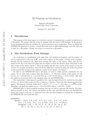
मान लीजिए $s = 1$, वर्ग के कोने बिंदुओं को इस प्रकार परिभाषित किया गया है: $p_0 = (0,0,0)$, $p_1 = (1,0,0)$, $p_2 = (1,1,0)$, $p_3 = (0,1,0)$। सामान्य रेखा z-अक्ष है जो $(0.5, 0.5, 0)$ से गुजरती है। शीर्ष और आधार के शीर्ष बिंदु $p_4$ और $p_5$ $(0.5, 0.5, \hat{z})$ से किसी भी कोने बिंदु तक की दूरी के समीकरण को हल करके प्राप्त किए जाते हैं: $(0.5)^2 + (0.5)^2 + \hat{z}^2 = 1^2$। इससे $\hat{z} = \pm\sqrt{0.5} \approx \pm 0.707$ प्राप्त होता है। इसलिए, $p_4 = (0.5, 0.5, 0.707)$, $p_5 = (0.5, 0.5, -0.707)$।
2.3 OpenSCAD कार्यान्वयन
3D मॉडल उत्पन्न करने के लिए OpenSCAD कोड में शीर्ष बिंदुओं और फलकों को परिभाषित करें। फलकों को शीर्ष बिंदु सूचकांकों को दक्षिणावर्त क्रम में सूचीबद्ध करके परिभाषित किया जाता है।
polyhedron(
यह एक गणितीय रूप से सटीक मॉडल बनाता है जिसे सीधे प्रिंट नहीं किया जा सकता (PDF में चित्र 1)।
3. 3D प्रिंटिंग के लिए ऑक्टाहेड्रॉन
गणितीय मॉडल को भौतिक निर्माण के अनुकूल बनाने के लिए, 3D प्रिंटिंग तकनीक की व्यावहारिक बाधाओं को हल करने की आवश्यकता है।
3.1 निर्माण संबंधी बाधाएँ
दो प्रमुख समस्याओं की पहचान की गई: 1) मॉडल की इकाई लंबाई (1 इकाई) मिलीमीटर-आधारित विशिष्ट 3D प्रिंटर के लिए बहुत छोटी है, जिसके लिए स्केलिंग की आवश्यकता है। 2) वस्तु को बिल्ड प्लेट (xy तल) पर एक स्थिर, समतल आधार होना चाहिए। केवल मॉडल को इस प्रकार स्थानांतरित करना कि एक शीर्ष बिल्ड प्लेट को स्पर्श करे, पर्याप्त नहीं है क्योंकि एक नुकीला बिंदु स्थिरता प्रदान नहीं कर सकता।
सभी शीर्षों पर घूर्णन $R$ लागू करने के बाद (और फिर स्केलिंग), एक स्थिर, प्रिंट करने योग्य, xy-तल पर सपाट पड़ा हुआ अष्टफलक प्राप्त होता है। परिवर्तित शीर्ष (तीन दशमलव स्थानों तक) हैं:
4. मूल विश्लेषण एवं तकनीकी अंतर्दृष्टि
मूल अंतर्दृष्टि:Aboufadel का कार्य शुद्ध गणितीय मॉडलिंग और वास्तविक डिजिटल निर्माण के बीच अक्सर अनदेखी की जाने वाली खाई का एक उत्कृष्ट उदाहरण है। यह एक महत्वपूर्ण तथ्य को उजागर करता है: ज्यामितीय रूप से परिपूर्ण CAD मॉडल अक्सर निर्माण में विफल होते हैं। इस पेपर का वास्तविक मूल्य अष्टफलक के शीर्षों की व्युत्पत्ति (एक पहले से हल की गई समस्या) में नहीं, बल्कि डिजिटल-भौतिक खाई को पाटने के लिए आवश्यक पोस्ट-प्रोसेसिंग चरणों (घूर्णन, स्केलिंग) के सूक्ष्म दस्तावेजीकरण में है। यहMIT सेंटर फॉर बिट्स एंड एटॉम्सके निष्कर्षों के अनुरूप है, जो इस बात पर जोर देता है कि "निर्माण के लिए डिज़ाइन" कम्प्यूटेशनल डिजाइन से एक अलग अनुशासन है।
तार्किक प्रवाह:यह लेख एक निर्दोष इंजीनियरिंग वर्कफ़्लो का अनुसरण करता है: 1)परिभाषित करें(ज्यामितीय बाधाएँ), 2)हल करें(निर्देशांक गणना), 3)कार्यान्वित करें(OpenSCAD कोड), 4)अनुकूलन(निर्माण के लिए)। यह एडिटिव मैन्युफैक्चरिंग अनुसंधान में मानक प्रक्रिया को दर्शाता है, जैसा किAdditive Manufacturingजर्नलों आदि में सिंहावलोकनों में रेखांकित किया गया है। हालांकि, यह प्रक्रिया स्पष्ट रूप से इस बात को उजागर करती है कि चरण 4 अनिवार्य है और अक्सर प्रारंभिक डिजाइन की तुलना में अधिक जटिल है।
लाभ और सीमाएँ:इसकी ताकत शैक्षिक स्पष्टता और व्यावहारिक क्रियान्वयन में है। यह एक संपूर्ण, पुनरुत्पादनीय "नुस्खा" प्रदान करता है। उद्योग के दृष्टिकोण से, इसकी सीमा इसके मैनुअल, एकल-उद्देश्यीय स्वरूप में है। रोटेशन कोण $\alpha$ इस विशिष्ट मामले के लिए विश्लेषणात्मक रूप से हल किया गया था। पेशेवर CAD/CAE सॉफ्टवेयर में, यह स्वचालित रूप से एक कंस्ट्रेंट सॉल्वर या जेनरेटिव डिज़ाइन एल्गोरिदम द्वारा किया जाएगा, जो स्वचालित रूप से प्रिंट दिशा और समर्थन न्यूनीकरण पर विचार करेगा, जैसे कि ऑटोडेस्क नेटफैब या सीमेंस एनएक्स जैसे टूल। इस पत्र में प्रस्तुत विधि जटिल, गैर-नियमित ज्यामिति तक विस्तारित नहीं की जा सकती।
क्रियान्वयन योग्य अंतर्दृष्टि:शिक्षकों के लिए, यह गणित और इंजीनियरिंग को एकीकृत करने वाला एक आदर्श STEM मॉड्यूल है। व्यवसाय में लगे पेशेवरों के लिए, मुख्य टेकअवे यह है किहमेशानिर्माण अक्ष और आधार स्थिरता पर शुरुआत से ही विचार करें। यह प्रक्रिया प्रारंभिक समन्वय प्रणाली के चयन का मार्गदर्शन करनी चाहिए। इसके अलावा, यह केस स्टडी ओपनएससीएडी जैसे ओपन-सोर्स टूल्स के लिए "प्रिंटेबिलिटी चेक" प्लगइन्स विकसित करने की आवश्यकता को प्रदर्शित करती है, ताकि इस पेपर में मैन्युअल रूप से किए गए विश्लेषण को स्वचालित किया जा सके। भविष्य निर्माण संबंधी बाधाओं को जेनरेटिव डिज़ाइन लूप में सीधे एम्बेड करने में है।
तकनीकी विवरण एवं सूत्र
मुख्य समीकरण (दूरी): $(x_1-x_2)^2 + (y_1-y_2)^2 + (z_1-z_2)^2 = s^2$। शीर्ष $p_4, p_5$ के लिए $\hat{z}$ ज्ञात करने हेतु प्रयुक्त।
मुख्य समीकरण (घूर्णन): $\frac{1}{2}\sin\alpha + \frac{\sqrt{2}}{2}\cos\alpha = 0$। $R p_4$ के z-घटक के शून्य होने की शर्त से व्युत्पन्न।
हल: $\tan\alpha = -\sqrt{2}$ से, $\sin\alpha = \sqrt{2/3}$, $\cos\alpha = -\sqrt{1/3}$, $\alpha \approx -54.74^\circ$ प्राप्त होता है।
परिवर्तन:सभी शीर्षों $p_0...p_5$ पर मैट्रिक्स $R$ लागू करें, ताकि प्रिंट करने योग्य निर्देशांक $\hat{p}_0...\hat{p}_5$ प्राप्त हो सकें।
प्रयोगात्मक परिणाम और ग्राफ़ विवरण
यह पेपर दो प्रमुख दृश्य परिणाम (चित्र) प्रस्तुत करता है:
चित्र 1 (प्रारंभिक मॉडल):पहले OpenSCAD कोड स्निपेट द्वारा उत्पन्न गणितीय रूप से सही ऑक्टाहेड्रॉन का रेंडर किया गया है। यह एक ऐसा आकार दिखाता है जिसमें एक शीर्ष सीधे वर्गाकार आधार के ऊपर और एक शीर्ष सीधे आधार के नीचे स्थित है; यदि प्रिंट किया जाता है, तो मॉडल एक नुकीले बिंदु पर संतुलन बनाए रखेगा।
चित्र 2 (मुद्रण योग्य मॉडल):रोटेशन मैट्रिक्स $R$ लागू करने के बाद का अष्टफलक दिखाया गया है। मुख्य दृश्य अंतर यह है कि अब एक त्रिकोणीय फलक क्षैतिज तल (आभासी निर्माण प्लेट) के साथ समतल है, जिससे एक स्थिर, समतल आधार बनता है। सभी शीर्षों के गैर-ऋणात्मक z-निर्देशांक हैं, जो z=0 से परत-दर-परत निर्माण के लिए इसकी उपयुक्तता की पुष्टि करते हैं।
इन दो अलग-अलग मॉडलों का सफलतापूर्वक निर्माण, गणितीय व्युत्पत्ति और परिवर्तन चरणों की आवश्यकता को सत्यापित करता है।
5. विश्लेषणात्मक रूपरेखा एवं केस उदाहरण
"3D प्रिंटिंग-उन्मुख डिजाइन" विश्लेषणात्मक ढांचा:
यह लेख किसी भी ज्यामितीय मॉडल को योगात्मक निर्माण के लिए परिवर्तित करने हेतु एक ढांचे का अंतर्निहित रूप से उपयोग करता है। इसके चरणों को इस प्रकार औपचारिक रूप दिया जा सकता है:
ज्यामितीय परिभाषा:वस्तुओं को गणितीय बाधाओं (शीर्ष, फलक, समीकरण) का उपयोग करके परिभाषित करें।
डिजिटल प्रोटोटाइपिंग:3D मेष उत्पन्न करने के लिए परिभाषाओं को CAD सॉफ़्टवेयर (जैसे OpenSCAD, Python स्क्रिप्ट) में लागू करें।
प्रिंट योग्यता ऑडिट:भौतिक बाधाओं के विरुद्ध जाँच करें:
आधार स्थिरता:क्या कोई फलक/क्षेत्र निर्माण प्लेट को स्पर्श करता है?
अभिविन्यास:क्या यह दिशा ओवरहैंग को कम करती है या सहारे की आवश्यकता को कम करती है?
स्केलिंग:क्या आयाम प्रिंट करने योग्य सीमा के भीतर हैं? (उदाहरण के लिए, मिलीमीटर पैमाने पर)
संरचनात्मक अखंडता:क्या कोई असमर्थित विशेषताएं हैं जो विफल हो सकती हैं?
मॉडल परिवर्तन:चरण 3 की समीक्षा आवश्यकताओं को पूरा करने के लिए ज्यामितीय परिवर्तन (स्थानांतरण, घूर्णन, स्केलिंग) लागू करें।
फ़ाइल निर्यात और स्लाइसिंग:मानक प्रारूप (STL, 3MF) में निर्यात करें और G-कोड उत्पन्न करने के लिए स्लाइसर सॉफ़्टवेयर में प्रसंस्करण करें।
केस उदाहरण (एप्लिकेशन फ्रेमवर्क): समस्या:10mm भुजा वाला एक नियमित टेट्राहेड्रॉन प्रिंट करें। 步骤1 & 2:शीर्षों को परिभाषित करें, उदाहरण के लिए (0,0,0), (10,0,0), (5, 8.66, 0), (5, 2.89, 8.16)। CAD में मॉडल बनाएं। चरण 3 समीक्षा:मॉडल को एक त्रिभुजाकार फलक पर रखा गया है (अच्छी स्थिरता)। हालाँकि, इस फलक के शीर्षों का z=0 है और फलक के भीतर के बिंदुओं का भी z=0 है, जिससे एक आदर्श आधार बनता है। स्केलिंग सही है (10mm)। चरण 4 परिवर्तन:इस स्थिति में, प्रारंभिक अभिविन्यास पहले से ही इष्टतम है। किसी घूर्णन की आवश्यकता नहीं है, संभवतः केवल मॉडल को बिल्ड प्लेट पर केंद्रित करने के लिए अनुवाद की आवश्यकता हो सकती है।
यह उदाहरण दर्शाता है कि कैसे यह ढांचा निर्णय लेने में मार्गदर्शन कर सकता है, जो ट्रायल-एंड-एरर विधि की तुलना में समय और सामग्री की बचत कर सकता है।
6. भविष्य के अनुप्रयोग एवं दिशाएँ
प्रदर्शित सिद्धांत एक एकल बहुफलक से परे व्यापक महत्व रखते हैं:
शैक्षिक टूलकिट:इस प्रक्रिया को स्वचालित करें, OpenSCAD या Blender जैसे प्लेटफार्मों के लिए सॉफ्टवेयर प्लगइन विकसित करें, जो छात्रों को प्लेटोनिक ठोस पैरामीटर दर्ज करने और स्वचालित रूप से अनुकूलित, मुद्रण योग्य मॉडल उत्पन्न करने की अनुमति दे।
उन्नत जालक एवं मेटामटीरियल्स:जटिल आवधिक सेल संरचनाएँ, जो एयरोस्पेस और बायोमेडिकल इम्प्लांट्स में महत्वपूर्ण हैं (प्रेरणालॉरेंस लिवरमोर नेशनल लेबोरेटरीआर्किटेक्चरल मटीरियल्स पर शोध से), जिन्हें प्रिंटेबिलिटी और यांत्रिक गुणों को सुनिश्चित करने के लिए समान ओरिएंटेशन ऑप्टिमाइज़ेशन की आवश्यकता है।
जेनरेटिव AI के साथ एकीकरण:टेक्स्ट-टू-3D या इमेज-टू-3D AI मॉडल को डाउनस्ट्रीम "प्रिंटेबिलिटी ऑप्टिमाइज़र" मॉड्यूल के साथ जोड़ना। AI आकृतियाँ उत्पन्न करता है, और ऑप्टिमाइज़र निर्माण हेतु अनुकूलित करने के लिए इस पेपर के तर्क से प्राप्त नियमों का उपयोग करके उन्हें समायोजित करता है।
बहु-सामग्री एवं सपोर्ट-मुक्त प्रिंटिंग:भविष्य का विकास ऐसे एल्गोरिदम को शामिल कर सकता है जो न केवल मॉडल का पुनः अभिविन्यास करते हैं, बल्कि सपोर्ट-मुक्त प्रिंटिंग को सुविधाजनक बनाने के लिए मॉडल को उप-घटकों में विभाजित करने या विभिन्न सामग्रियों को आवंटित करने का सुझाव भी देते हैं, जो आधुनिक एडिटिव मैन्युफैक्चरिंग का एक प्रमुख शोध क्षेत्र है।
"प्रिंटेबिलिटी स्कोर" मानकीकरण:सफलता दर की भविष्यवाणी करने के लिए ज्यामिति और प्रिंटर क्षमताओं पर आधारित मात्रात्मक मापदंड विकसित करना, जैसे किInternational Journal of Advanced Manufacturing Technologyमें उद्धृत कार्य।
7. संदर्भ साहित्य
Aboufadel, E. (2014). 3D Printing an Octohedron. Grand Valley State University. arXiv:1407.5057v1.
Gibson, I., Rosen, D., & Stucker, B. (2021). एडिटिव मैन्युफैक्चरिंग तकनीकें: 3D प्रिंटिंग, रैपिड प्रोटोटाइपिंग और डायरेक्ट डिजिटल मैन्युफैक्चरिंग। Springer. (एडिटिव मैन्युफैक्चरिंग के लिए व्यापक डिजाइन सिद्धांतों के बारे में)।
MIT Center for Bits and Atoms. (2023). अनुसंधान: डिजिटल मैन्युफैक्चरिंग। https://cba.mit.edu/ से पुनर्प्राप्त। (डिजाइन से निर्माण एकीकरण की अवधारणा के बारे में)।
Zhu, J., et al. (2017). अनपेयर्ड इमेज-टू-इमेज ट्रांसलेशन के लिए साइकल-कंसिस्टेंट एडवरसैरियल नेटवर्क्स का उपयोग। ICCV. (ट्रांसफॉर्मेशन मॉडल के उदाहरण के रूप में CycleGAN, मॉडल ट्रांसफॉर्मेशन चरण के समान)।
Brackett, D., Ashcroft, I., & Hague, R. (2011). एडिटिव मैन्युफैक्चरिंग के लिए टोपोलॉजी ऑप्टिमाइजेशन। Proceedings of the Solid Freeform Fabrication Symposium। (एडिटिव मैन्युफैक्चरिंग के लिए स्वचालित डिज़ाइन ऑप्टिमाइजेशन पर उन्नत पृष्ठभूमि)।
International Journal of Advanced Manufacturing Technology। (विविध)। एडिटिव मैन्युफैक्चरिंग के लिए डिज़ाइन विशेषांक। Springer। (प्रिंटेबिलिटी विश्लेषण में नवीनतम प्रगति पर)।
मूल अंतर्दृष्टि:Aboufadel का कार्य शुद्ध गणितीय मॉडलिंग और वास्तविक डिजिटल निर्माण के बीच अक्सर अनदेखी की जाने वाली खाई का एक उत्कृष्ट उदाहरण है। यह एक महत्वपूर्ण तथ्य को उजागर करता है: ज्यामितीय रूप से परिपूर्ण CAD मॉडल अक्सर निर्माण में विफल होते हैं। इस पेपर का वास्तविक मूल्य अष्टफलक के शीर्षों की व्युत्पत्ति (एक पहले से हल की गई समस्या) में नहीं, बल्कि डिजिटल-भौतिक खाई को पाटने के लिए आवश्यक पोस्ट-प्रोसेसिंग चरणों (घूर्णन, स्केलिंग) के सूक्ष्म दस्तावेजीकरण में है। यहMIT सेंटर फॉर बिट्स एंड एटॉम्सके निष्कर्षों के अनुरूप है, जो इस बात पर जोर देता है कि "निर्माण के लिए डिज़ाइन" कम्प्यूटेशनल डिजाइन से एक अलग अनुशासन है।
तार्किक प्रवाह:यह लेख एक निर्दोष इंजीनियरिंग वर्कफ़्लो का अनुसरण करता है: 1)परिभाषित करें(ज्यामितीय बाधाएँ), 2)हल करें(निर्देशांक गणना), 3)कार्यान्वित करें(OpenSCAD कोड), 4)अनुकूलन(निर्माण के लिए)। यह एडिटिव मैन्युफैक्चरिंग अनुसंधान में मानक प्रक्रिया को दर्शाता है, जैसा किAdditive Manufacturingजर्नलों आदि में सिंहावलोकनों में रेखांकित किया गया है। हालांकि, यह प्रक्रिया स्पष्ट रूप से इस बात को उजागर करती है कि चरण 4 अनिवार्य है और अक्सर प्रारंभिक डिजाइन की तुलना में अधिक जटिल है।
लाभ और सीमाएँ:इसकी ताकत शैक्षिक स्पष्टता और व्यावहारिक क्रियान्वयन में है। यह एक संपूर्ण, पुनरुत्पादनीय "नुस्खा" प्रदान करता है। उद्योग के दृष्टिकोण से, इसकी सीमा इसके मैनुअल, एकल-उद्देश्यीय स्वरूप में है। रोटेशन कोण $\alpha$ इस विशिष्ट मामले के लिए विश्लेषणात्मक रूप से हल किया गया था। पेशेवर CAD/CAE सॉफ्टवेयर में, यह स्वचालित रूप से एक कंस्ट्रेंट सॉल्वर या जेनरेटिव डिज़ाइन एल्गोरिदम द्वारा किया जाएगा, जो स्वचालित रूप से प्रिंट दिशा और समर्थन न्यूनीकरण पर विचार करेगा, जैसे कि ऑटोडेस्क नेटफैब या सीमेंस एनएक्स जैसे टूल। इस पत्र में प्रस्तुत विधि जटिल, गैर-नियमित ज्यामिति तक विस्तारित नहीं की जा सकती।
क्रियान्वयन योग्य अंतर्दृष्टि:शिक्षकों के लिए, यह गणित और इंजीनियरिंग को एकीकृत करने वाला एक आदर्श STEM मॉड्यूल है। व्यवसाय में लगे पेशेवरों के लिए, मुख्य टेकअवे यह है किहमेशानिर्माण अक्ष और आधार स्थिरता पर शुरुआत से ही विचार करें। यह प्रक्रिया प्रारंभिक समन्वय प्रणाली के चयन का मार्गदर्शन करनी चाहिए। इसके अलावा, यह केस स्टडी ओपनएससीएडी जैसे ओपन-सोर्स टूल्स के लिए "प्रिंटेबिलिटी चेक" प्लगइन्स विकसित करने की आवश्यकता को प्रदर्शित करती है, ताकि इस पेपर में मैन्युअल रूप से किए गए विश्लेषण को स्वचालित किया जा सके। भविष्य निर्माण संबंधी बाधाओं को जेनरेटिव डिज़ाइन लूप में सीधे एम्बेड करने में है।